
Why This Companion Is Here
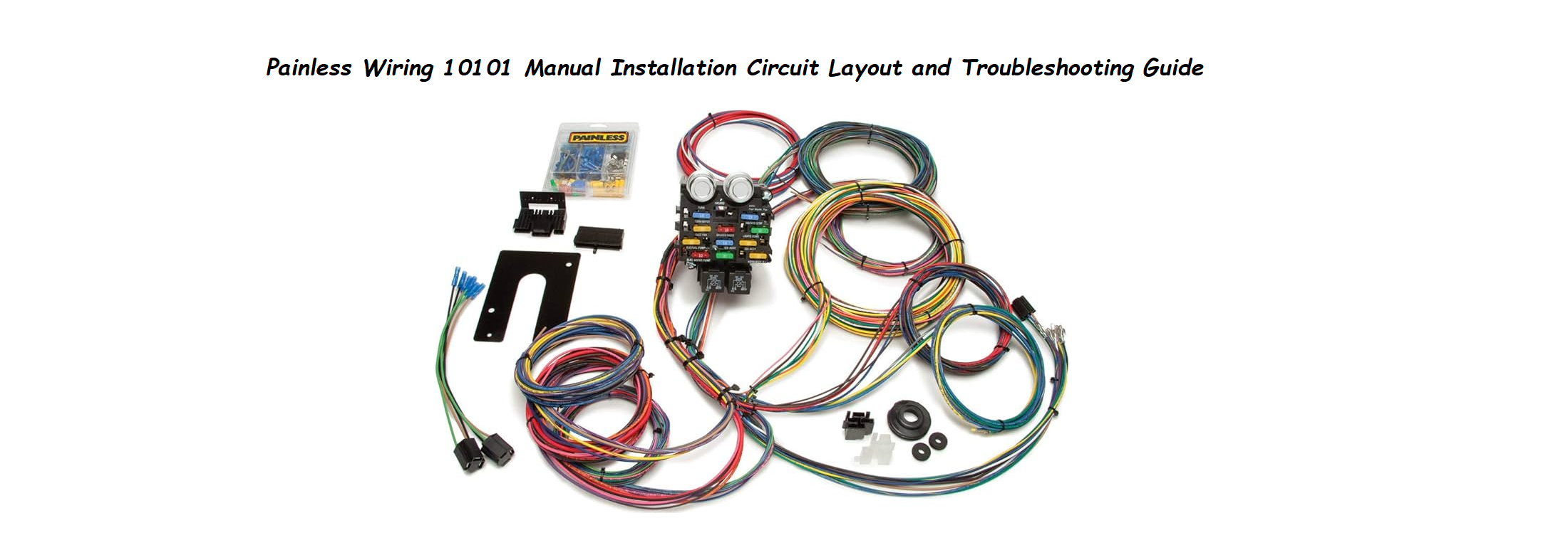
Painless Performance ships the 10101 universal wiring harness with a large bundle of colour‑coded wires, a fuse block, connectors, and a thick printed instruction booklet. That booklet is thorough, but it reads like a telephone directory. Real‑world builders often search for a “Painless Wiring 10101 manual” because they want clear, step‑by‑step help with reading the wire labels, mounting the fuse panel, making solid crimped connections, and troubleshooting dead circuits. This companion gives you exactly that — plain language, no assumptions.
What’s in the Box
Your kit includes:
- The main wiring harness bundle (over 20 circuits, each wire labelled every 6 inches)
- A pre‑wired fuse block with blade‑type fuses
- Two turn‑signal flasher units (one for turn signals, one for hazards)
- A horn relay
- A headlight and ignition switch wiring section with connectors
- A large assortment of terminals, connectors, and heat‑shrink tubing
- Zip ties and mounting hardware
- A thick printed instruction booklet
The harness is designed for 12‑volt, negative‑ground vehicles. It can be installed in any make or model, but it is not a direct‑fit replacement; you will need to route, cut, and terminate each wire.
Understanding the Fuse Block and Circuit Layout
The heart of the harness is the compact fuse block. It must be mounted inside the vehicle, typically under the dash on the driver’s side, away from water and heat.
- Fuse positions: Each circuit is clearly labelled on the block. Common circuits include IGN (ignition), ACC (accessories), WIPER, RADIO, HEAT/AC, TURN, HAZARD, HEADLIGHT, BRAKE, TAIL, DOME, and SPARE. The labels correspond to the wire labels.
- Pre‑installed fuses: The kit comes with the correct amperage fuses already installed. Do not replace them with higher‑rated fuses.
- Relays: The headlights and horn relay are external to the block. Mount them on a metal surface near the radiator support or firewall.
- Grounds: The harness has multiple black ground wires. You must connect them to clean, bare metal on the chassis and engine block. A poor ground causes 90% of electrical gremlins.
Reading the Wire Labels and Colour Code
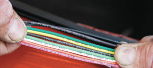
Every wire is labelled with its circuit name and sometimes a number. The labels are printed every 6 inches, so you can identify the wire even after trimming it.
- Example labels: “HEADLIGHT SW – BAT,” “LEFT TURN,” “FUEL PUMP,” “DOME LIGHT,” “COIL +”
- Colour coding follows industry standards, but the printed labels are your primary identification. Use them to route each wire to the correct component.
- Extra length: The wires are intentionally long. Route them first, leaving extra loops, then cut to the exact length before terminating. Do not pull the harness tight; allow slack for engine movement and future repairs.
Making Proper Connections: Crimping and Soldering
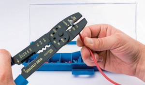
The kit includes a variety of terminals: ring, spade, bullet, and butt connectors. Good connections are crucial.
- Strip the wire: Use a quality wire stripper to remove about 1/4 inch of insulation. Do not nick the copper strands.
- Crimping: Select the correct terminal size (red for 18‑22 gauge, blue for 14‑16 gauge, yellow for 10‑12 gauge). Slide the bare end into the terminal barrel. Use a ratcheting crimp tool for the strongest connection. Squeeze until the tool releases. Tug firmly to test.
- Soldering (optional): For the most durable connection, solder the wire after crimping. Heat the terminal with a soldering iron and feed a small amount of rosin‑core solder into the wire end. Do not let solder flow under the insulation.
- Heat‑shrink: Slide a piece of heat‑shrink tubing over the connection before mating. After connecting, move the tubing over the joint and heat with a heat gun or lighter until it shrinks tight. The kit includes pre‑cut pieces; use them on every outdoor connection.
Avoid using wire nuts or twist‑and‑tape methods. They will fail in a vehicle.
Troubleshooting Common Issues
| Problem | Likely Cause | What to Try |
|---|---|---|
| No power to the entire fuse block | Main power wire not connected or fuse blown | Check the large red wire from the battery to the fuse block main terminal. Ensure the MAXI‑fuse (if included) or your inline main fuse is not blown. |
| A single circuit is dead | Blown fuse, broken wire, or bad ground | Check the fuse for that circuit in the block. Test the wire with a multimeter. Clean the ground point for that circuit. |
| Turn signals flash too fast or too slow | Wrong flasher unit or mixed bulb types | Ensure you are using the correct flasher (included). If replacing bulbs with LEDs, you need an LED‑compatible flasher. |
| Headlights flicker or are dim | Bad ground or relay fault | Clean the headlight ground. Swap the relay with a known good one (horn relay is the same type). |
| Wipers run but won’t park | Park wire not connected | The harness has a dedicated wiper park wire. Connect it to the “PARK” terminal on your wiper motor. |
| Horn doesn’t work | Relay not grounded or wire broken | Ensure the relay is securely grounded. Jumper the relay terminals briefly to test the horn directly. |
How to Test Circuits and Reset the Harness
The harness itself doesn’t have a reset button, but you can troubleshoot by isolating circuits.
- Use a multimeter: Set to DC voltage. Probe the fuse block terminals to verify power. Check continuity (ohms) between ground wires and the chassis (should be near 0 ohms).
- Jumper test: To test a component, you can temporarily bypass the harness by running a fused jumper wire from the battery to the component. If it works, the harness has a fault.
- Re‑check all main connections: The large ring terminals at the starter solenoid, alternator, and battery must be clean and tight.
Quick Reference Card
| Task | How |
|---|---|
| Identify a wire | Read the printed label every 6 inches |
| Crimp a terminal | Strip 1/4 inch, insert into terminal, compress with crimp tool, tug test |
| Test for power | Multimeter on DC voltage, probe circuit terminal to ground |
| Ground a circuit | Connect black ground wire to clean, bare metal on chassis |
| Mount fuse block | Inside vehicle, under dash, away from water, using provided screws |
| Replace a fuse | Pull old fuse from block, insert same amperage, press firmly |